Nomenclature and Definitions
Ultrasonic Testing (UT/PAUT)
General definitions
Ultrasonic Testing (UT)
Non-destructive testing technique that uses high-frequency sound waves to detect internal discontinuities or to measure material thickness. A single transducer is typically used.
Phased Array Ultrasonic Testing (PAUT)
Advanced UT technique using a probe with multiple elements that can be electronically controlled to steer, focus, and scan the beam without physically moving the probe.
Full Matrix Capture (FMC)
Acquisition mode where every element transmits individually while all elements receive, capturing the complete set of elementary A-scans for post-processing (e.g. TFM).
Total Focusing Method (TFM)
Post-processing reconstruction algorithm applied to FMC data that synthetically focuses the beam at every point of a reconstruction grid.
Plane Wave Imaging (PWI)
Acquisition mode where unfocused plane waves are transmitted and received by all elements, enabling high frame-rate imaging.
Probe and beam definitions
Element
Individual piezoelectric transducer unit within a probe. In PAUT, multiple elements are combined and electronically controlled to form a beam.
Aperture
The set of elements that are actively used for a given transmission or reception event.
Pitch
Center-to-center distance between adjacent elements in an array probe.
Focal law
Set of time delays applied to each element of a phased array probe to steer and/or focus the ultrasonic beam at a desired angle and depth.
Refracted angle
Angle of the ultrasonic beam in the inspected material, measured from the normal to the surface.
Wedge delay
Time offset applied to account for the travel time of the ultrasonic beam through the wedge material before entering the specimen.
Wave mode
Type of ultrasonic wave propagating in the material. Common modes are:
- Longitudinal (L): Particle motion is parallel to the propagation direction.
- Transversal (T): Particle motion is perpendicular to the propagation direction (also called shear wave).
Acquisition and scan types
A-scan
Time-based waveform representing the amplitude of the ultrasonic signal received by the probe as a function of time (or depth). It is the fundamental data unit.
C-scan
Image of the inspected area where the displayed value (e.g. peak amplitude or time-of-flight) is extracted from the A-scan within a defined gate.
Gate
Time window applied to an A-scan to extract amplitude, time-of-flight, or other characteristics from a specific region of interest.
Pulse-echo
Acquisition mode where the same element(s) are used for both transmission and reception.
Pitch-catch
Acquisition mode where different element(s) are used for transmission and reception, allowing inspection of different propagation paths.
TOFD (Time-of-Flight Diffraction)
Technique using two probes in pitch-catch configuration where diffracted signals from crack tips are used to size and locate defects.
Linear scan
PAUT scan type where the focal laws sequentially shift the active aperture along the array, producing a B-scan image.
Sectorial scan (S-scan)
PAUT scan type where the beam is steered over a range of angles at a fixed aperture, producing a fan-shaped image.
Compound scan
PAUT scan type combining both aperture shifting and angular steering.
Signal processing and calibration
TCG (Time-Corrected Gain)
Amplification profile applied as a function of time to compensate for signal attenuation with depth, ensuring uniform sensitivity throughout the inspected volume.
DAC (Distance-Amplitude Correction)
Calibration curve that accounts for signal amplitude variation as a function of distance for reflectors of equal size, used to set acceptance thresholds.
Digitizing frequency
Sampling rate of the analog-to-digital converter (ADC), expressed in Hz.
Rectification
Processing step applied to the A-scan waveform to convert the RF signal into a unipolar (half-wave or full-wave rectified) signal.
Eddy Current Testing (ECT/ECA)
General definitions
Eddy Current Testing (ECT)
Probe and instrumentation technology based on having sensor(s) each individually providing scan coverage.
Eddy Current Array (ECA)
Probe and instrumentation technology based on having multiple identical sensors working together in order to achieve a given scan.
Probe-related definitions
Physical component
Basic building blocks of an array probe, including active components such as coils, GMR, AMR or Hall effect probes, and passive components such as ferromagnetic and/or conductive parts whose shape and location are purposely designed to modify a sensor's response.
Element
Arrangement of physical component(s) which has a basic function of excitation or reception. Components can be re-used for multiple elements; for example, a coil can be an excitation element in one time slot and a component of a reception element in other time slots.
Sensor
Physical and electronic arrangement of excitation element and reception elements designed to provide the desired detection and measurement of physical properties based on the principles of eddy current testing.
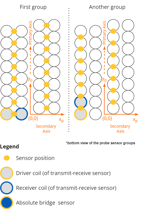
Pattern (specific to arrays)
Physical sensors distribution within an array on the sensor surface. For example, a given sensor's pattern could be described by a set of primary axis and secondary axis offsets relative to a reference position. Multiple sensor groups can co-exist in the same probe with a defined pattern for each.
Instrumentation-related definitions
Input
Physical analog connection on the acquisition unit corresponding to the entry point of sensor(s) reading measurements.
Time-slot (or Context)
When using time multiplexing to add more channels on a given input, this is a specific time frame when a given input is connected to a specific sensor.
Channel
Specific band of eddy current inspection data related to the combined use of a sensor and inspection parameters (frequency, gain, drive parameters, calibration parameters, filtering, etc.). A channel can also be the result of processes applied on other channels (e.g. MIX).
Digitizing frequency [Hz]
Acquisition frequency of the Analog to Digital Converter (ADC).
Test frequency [Hz]
Carrier frequency of the sine wave leading to the generation of eddy currents.
Samples
Specific impedance readings that are the final outputs of the whole demodulation process.
Note
For Eddy Current Array applications: for a given channel there is no more than one sample per time slot.
Measurement rate [sample/s]
Rate of generation of samples; without further precision, this is for one specific input and one specific frequency.
Instrument measurement rate [sample/s]
Rate of generation of samples for a whole instrument.
Channel measurement rate [sample/s]
Rate of generation of samples for one specific channel.
Strip chart
By channel, uniformly distributed series of samples, where the uniform distribution can be over time (i.e. fixed frequency in Hertz) or over distance (i.e. fixed spatial frequency in 1/meter). Real and imaginary components of the signal are typically displayed separately after phase rotation by the user to isolate relevant signal on one component.
Impedance plane
Diagram displaying samples where the time or position axis is compressed and the user sees the complex representation of the data for the multiple points of a strip chart.